Paul C. Buff, Inc. Technical Forum
https://paulcbuff-techforum.com/

Technical question regarding (camera's) hot shoe circuit
https://paulcbuff-techforum.com/viewtopic.php?f=8&t=4656
Page 1 of 1

Author:  Sebastian [ Mon Dec 08, 2014 9:25 pm ]
Post subject:  Technical question regarding (camera's) hot shoe circuit

Hello-

I am an optical engineer by trade and a photographer just as a hobbyist. I don't know if this is the right place to ask, but I figured I would give it a shot. I realize this might be a conflict of interest but my intentions are not to create a flash trigger, I promise. I actually own two CSBs and multiple CSRBs.

I am wanting to build a circuit around a Nikon DSLR hot shoe. My intention is to us the camera's hot shoe/PC contact to initiate an external circuit and I am running into some issues. I was curious if anyone at Paul Buff or elsewhere would be willing to lend an ear to my application?

Basically I don't know how to interface with the camera despite multiple approaches. I would be more than willing to share my attempted circuits and o'scope trials. I just need to get a solid signal out of the camera. I've come close a few ways but I feel there is a better way to do it.

Many many thanks in advance,
Sebastian

http://www.sebastianstewart.com/

Author:  Technical Support [ Tue Dec 09, 2014 4:01 pm ]
Post subject:  Re: Technical question regarding (camera's) hot shoe circuit

I am not sure we are the best place to ask. Our engineering staff is quite busy, and I would not likely be of much help personally.

You are welcome to post, and there may be someone who can help, but I don't want to allude we can provide much value.

Author:  Mack [ Wed Dec 10, 2014 1:31 pm ]
Post subject:  Re: Technical question regarding (camera's) hot shoe circuit

Not hard to find. I just Googled "Nikon hot shoe contacts pinout" and got these:

http://dptnt.com/2010/04/nikon-flash-interface/

http://pinoutsguide.com/DigitalCameras/ ... nout.shtml

Nikon also makes some banana-lead cable for their cameras with the 10-pin sockets, but I think it has more to do with shutter and auto-focus controls than the flash. Might be in one of the 10 pins though, but I was only trying to fire the thing.

I also think the flash hot shoe contacts are controlled by some transistor or MOSFET circuit as I think I tried to use it one time and it took some minimal voltage and current to operate. Not just a simple switch. Some of my triggers also operate that way and caused me a bit of confusion as some flashed with low voltage at the shoe wouldn't fire, and others would. Thinking back, I think one had about 4 volts and wouldn't fire, but the other had maybe 8 volts and would which led me to believe it was not a simple switch in there?

I had an issue with Sekonic meter where their PC socket refused to fire a cabled flash and later learned it was also a transistorized switch that needed more voltage to trip the flash. No switch in it either, and the ohmmeter showed an open circuit if fired or not. Took someone else at Sekonic to mention that as I thought it was broken since the meter wouldn't show a closed circuit. First tech said it had to come in, then I got another who responded who said "The design didn't operate as a mechanical switch (short circuit) so an ohmmeter would always show open even if the button were held to fire the flash." Also said "A lot of trigger voltage may damage it too."

Good luck!

Author:  Sebastian [ Thu Dec 11, 2014 2:04 pm ]
Post subject:  Re: Technical question regarding (camera's) hot shoe circuit

Hey everyone, thanks for the prompt replies and sharing the links.

I actually found that first link you shared but (to me) I read mostly about the TTL protocol and not the more simple open/close feature of the center pin.

I did a bunch more research and found some very useful thing. I was able to get my circuit functional (AND! using less ICs that originally intended). I can share my findings here if the moderators feel it's a pertinent post and not conflicting with their own product line...


Cheers-
Sebastian

Author:  Technical Support [ Thu Dec 11, 2014 3:51 pm ]
Post subject:  Re: Technical question regarding (camera's) hot shoe circuit

As long as it is not competing with our products, and you are not trying to sell anything, I don't think it will be an issue. Ideally, it should be on topic of lighting.

Author:  Sebastian [ Tue Dec 16, 2014 12:13 pm ]
Post subject:  Re: Technical question regarding (camera's) hot shoe circuit

As it turns out I was probably doing something wrong when I first attempted this.... as the solution was fairly straightforward. I might give another few circuits a go and pick which variation I like the most.

Originally I was using an op-amp and a multivibrator IC to condition the output pulse from the camera but I made a much more simple circuit using a 555 timer in a one-shot configuration. Usually the 555 will start its timing when a negative pulse is applied to it's trigger (pin 2), but this setup uses a positive pulse to trigger the timing. I adjusted the RC constant to ensure the 555 output pulse is long enough for the rest of the circuit (not pictured).

Another one of my issues was the camera's internal SCR latching from too much current flowing through it. I adjusted R1 until this latching condition ceased, and then introduced a slight safety margin by using a slightly higher resistance.

The SCR circuit close time is dependent on the flash setting (at least on my camera). Rear curtain flash has a constant duration pulse independent of the shutter speed, and the normal flash mode produces a pulse that is directly proportional to the shutter speed.

I've included some other drawings and notes that helped me along the way - I hope this helps someone! Please do leave comments if you have them.

Cheers-
Sebastian


Image

Author:  Mack [ Tue Dec 16, 2014 11:14 pm ]
Post subject:  Re: Technical question regarding (camera's) hot shoe circuit

So you are making the sync contacts stay closed longer with the above circuit? Are you controlling something other than flash as I believe flash will fire in the initial firing of the opto-isolator above? I have a flash sequencer that operates much the same way firing 8 heads one after the other off a 556 and a decade counter (4011 ??) to the 8 opto-isolators.

An easier way for sync timing that I found was to use a Arduino Uno microprocesser from local Radio Shack along with a relay board they sell for it that holds four high current relays that plugs into the top of it. I ran mine off the using shutter's lag time off the 10 pin connector. That way, I can control the flash to fire 'ahead' of the shutter or behind it. I had to figure out a way to fire it 'ahead' of the shutter for use with Meggaflash PF-330 2-second burn time flash bulb that ramps up to maximum burn, and then the shutter needs to fire about 0.45 second after the bulb begins to burn and hit peak. Easy to do in Arduino's C-based programming language (Compiler is freeware!) and watching the LED's lighting for the relays on that PC board.

Another option is commercially available CameraAx (sp?) I think for varying the sync timing for $200.

Mack

Author:  Sebastian [ Tue Jan 06, 2015 12:04 pm ]
Post subject:  Re: Technical question regarding (camera's) hot shoe circuit

Mack-

Sorry for the delay, I caught quite the cold this holiday season!

The circuit isn't actually making the sync contacts stay closed longer per say. Instead, I am using the short time duration pulse of the sync contacts closing to activate another circuit which provides a longer pulse. I am controlling something other than a flash, yes, and it requires contact for >75ms.

In rear-curtain flash the sync contacts only close for perhaps 3-4ms, and in the normal flash mode the sync contacts are closed in direct relationship with the shutter speed (at least for at some shutter speed cutoff point).

During my downtime I bought an MC-23 cord used to connect two Nikon cameras together, and I cut it in half to expose all ten wires inside. I found these pinouts:

http://www.petermillerphoto.com/nikongp ... 10pins.gif
http://pinoutsguide.com/DigitalCameras/ ... nout.shtml

However, I can't seem to get at a true "shutter out" signal. I confirm that pin 3 goes high when the meter is active, but I want to have a pin go high once the shutter is actuated. The link seems to indicate that pin 8 has this duty, but I can't confirm this function with my o'scope.

You mention you ran your system using the shutter lag time on the 10-pin connector - what do you mean by this and how did you use this connector to do so?

I realize I can always use the hot shoe / pc sync, but how elegant would it be to use the 10-pin for ALL the requirements I need for my device?

Cheers, and let me know if you want to chat about this via email-
Sebastian

Author:  Mack [ Wed Jan 07, 2015 12:43 am ]
Post subject:  Re: Technical question regarding (camera's) hot shoe circuit

I went a different route. I used a Nikon remote cord with the 10 pin on the end.

This thing: http://www.nikonusa.com/en/Nikon-Produc ... lease.html

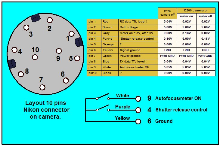
Taking out the screws out of the handle shows two micro-switches inside. It is a two-stage switch. The requirement for the shutter to operate is that the metering has to be active. Somehow Nikon arranged the power supply to provide the shutter firing voltage from the meter side, i.e. No meter on, no shutter. First half of the press turns on the meter and auto-focus, pressing more trips the shutter.

What I did was go to All Electronics in LA (Online catalog too.). Maybe $3 at most. They have a molded multi-wire that looks like the Nikon wire strain-relief grommet and it just about fits the Nikon remote handle perfectly with the molded strain relief. The ends are bare so you can attach them to whatever circuit you are doing.

I used the Arduino Uno as my timer. Problem is I had to leave the auto-focus off as that part can vary the timing depending on how fast the lens gets a lock. Not a big deal, but I have to manually focus. The meter works normally and fires the shutter in a fixed shutter lag as specified in some sites that review the camera for shutter lag. I think mine is 43ms with focus locked to OFF.

So when I press the remote for SW1, it operates the meter and flips the power on to SW2 so when I press further down on the button, it has the voltage to fire the shutter. That SW2 going active has the 43ms delay from SW2 triggering (closing), mirror flipping out of the way, and shutter activation.

My circuit had to keep the shutter from firing for 400ms so the flashbulb could come up to peak burn. So tripping SW2 for me, fires the PF-330 flashbulb off a 14 volt lithium battery via one relay in the "Relay Shield," and the Arduino Uno also times out a second relay delay (that I can easily set in the program) for the shutter to operate 400ms later (Actually 400ms-43ms or 357ms I think it was?). Actually there might be a third relay I used that operates the metering circuitry first, Relay 0 maybe? Been a while since I built it.

I was going to use a dual-trace scope with a mike and check the shutter trip signal and the quiet time once the shutter fired on Bulb and get my own lag time, but some published site's did that work already so I didn't need to. With the Arduino Uno, the timing is pretty accurate as it is since its microprocessor has an internal clock. Got me away from playing with the 555/556 timers too that had all sorts of triggering issues with times. Those were a pain for the couple of days learning the Arduino language. Plus their "Relay Shield" plug-in with 4 high current 120 volt 10 amp relays has LEDs next to each that gives me a visual cue as to the timing.

Worked pretty well in the field too. Kids never seen old-style flashbulbs go off and blister up so it was like a new light show to them.

Mack

Page 1 of 1 All times are UTC - 6 hours [ DST ]
Powered by phpBB® Forum Software © phpBB Group
https://www.phpbb.com/